KKmoon HW-210K Handheld Portable Dual-channel VI Curve Tester


Nedan kommer det som skall vara manualen. Kan upplevas som lite tunn, men testaren fungerar när du väl justerat in den.
KKmoon HW-210K Handheld Portable Dual-channel VI Curve Tester
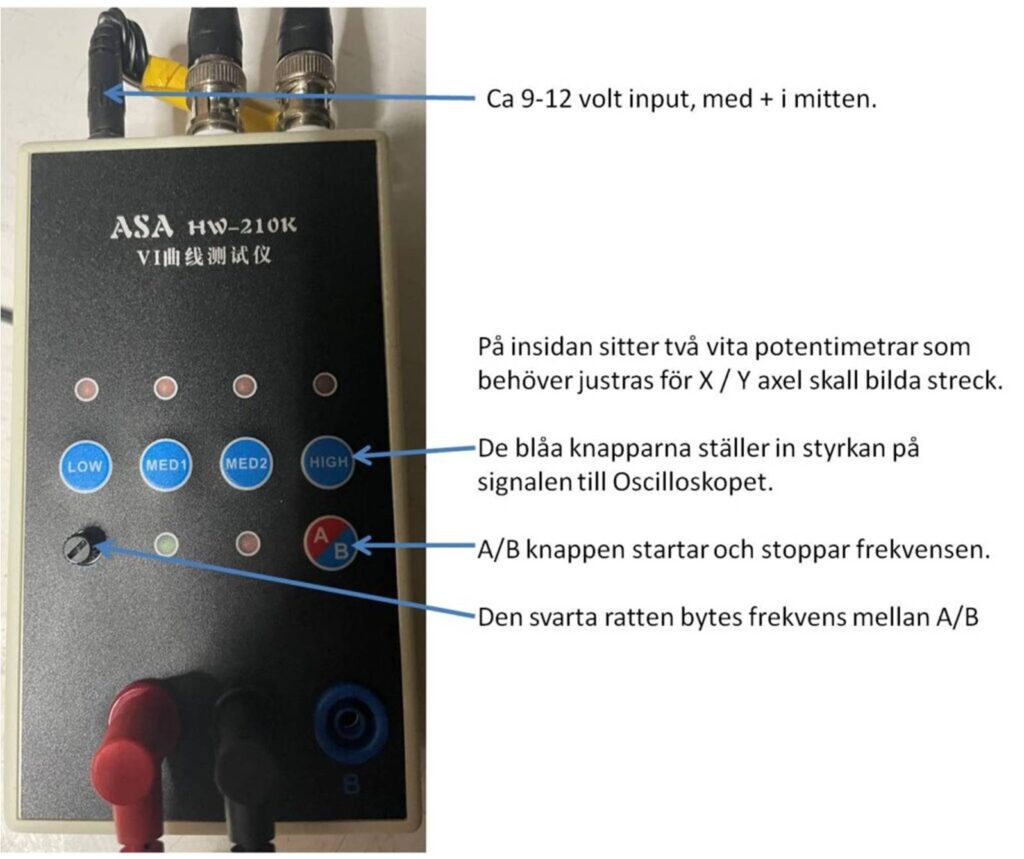
Circuit Board Online Detection ASA Tester 4 Gear (betyder i detta fall 4 olika singnalstyrkor/frekvenser) Frequency Alternating Speed Adjustable
Product details of KKmoon HW-210K Handheld Portable Dual-channel VI Curve Tester Circuit Board Online Detection ASA Tester 4 Gear Frequency Alternating Speed Adjustable
- 4 test frequencies, can be used when connected to an oscilloscope, both analogs oscilloscopes and digital oscilloscopes can be used.
- Dual signal input, alternating display function allows you to use it in easier.
- 4-gear frequency, alternating speed adjustable, you can adjust it according to your needs.
- One click on singles channel/alternating display, which can give you a better using experience.
- When testing the circuit board online, do not recharge the circuit board. If there is a large capacitor on the circuit board, discharge the capacitor first, otherwise it is easy to burn out the VI test board.
This handheld portable VI curve tester VI Curve has 4 test frequencies, can be used when connected to an oscilloscope, both analogs oscilloscopes and digital oscilloscopes can be used. If you are looking for this product, come and have a try, it will not let you down.
Features:
4 test frequencies, can be used when connected to an oscilloscope, both analogs oscilloscopes and digital oscilloscopes can be used.
Dual signal input, alternating display function allows you to use it in easier.
4-gear frequency, alternating speed adjustable, you can adjust it according to your needs.
One click on singles channel/alternating display, which can give you a better using experience.
When testing the circuit board online, do not recharge the circuit board. If there is a large capacitor on the circuit board, discharge the capacitor first, otherwise it is easy to burn out the VI test board.
Specifications:
Material: plastics
Channel: 2 channels
Frequency: 4 gears
Package size: 195 * 135 * 105mm / 7.7 * 5.3 * 4.1in
Package weight: 435g / 1.0lb
Method of connecting analogs oscilloscope:
The analogs oscilloscope connection is relatively simple, and different oscilloscopes are slightly different.
Adjust the oscilloscope to xY mode. Some oscilloscopes can be selected by pressing the buttons, while others are selected by the knob to xY mode. Please study by yourself.
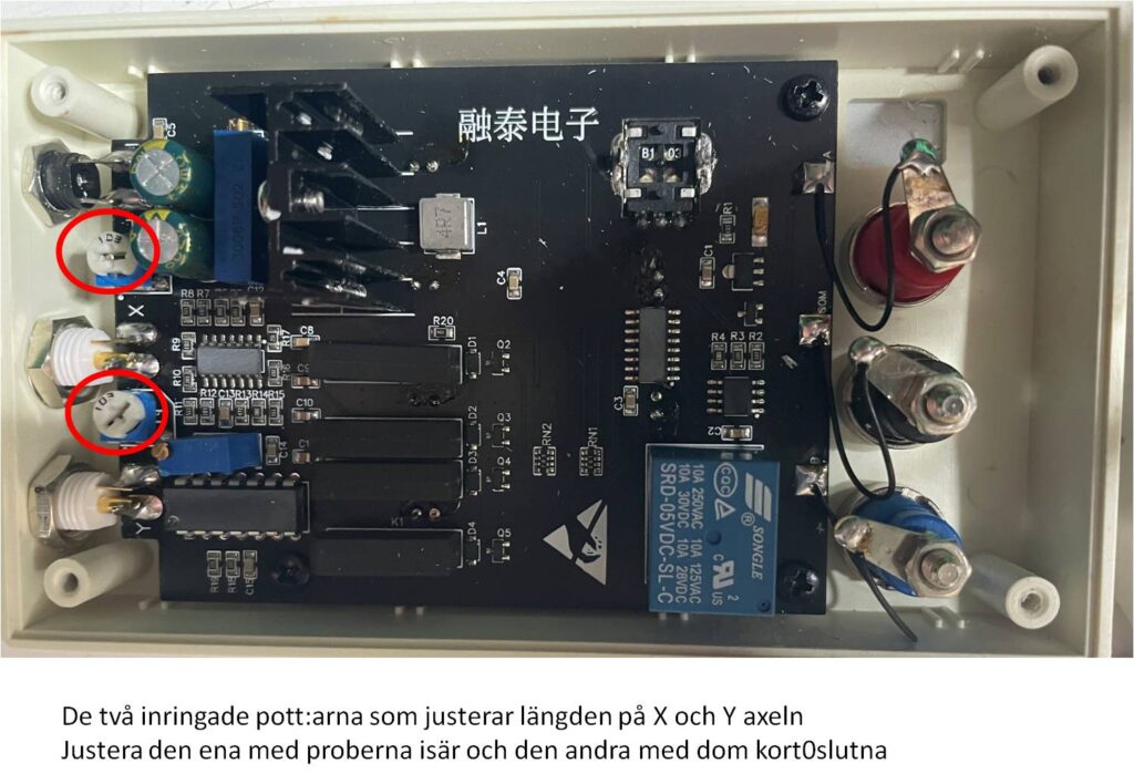
Connect the BNC cable to the oscilloscope and power on. Normally, a horizontal line will be displayed. Adjust the xY vertical channel parameters, about 1V/div, and then adjust the x Y attenuation so that the horizontal line is in the display frame. It can also pass the VI test version. The x attenuation potentiometer on the upper side can assist in adjusting the length of the horizontal line. If the test pen iis short-circuited, a vertical line will be displayed under normal circumstances. If the vertical line is too long or too short, you need to adjust the Y channel parameters to make the vertical line in the display frame. Half grids or 1 grids to the edges is better. If the horizontal and vertical lines are normal, you can enter the normal measurement.
How to connect a digital oscilloscope:
For digital oscilloscopes, enter the xY mode through the menu or keys. The two channels of xY are adjusted to 1V/div,and the single-track oscilloscope only needs to adjust the Y channel. Adjust the
base to 1-5 milliseconds. The xY channel selects Direct Current coupling, and the attenuation is 1x.
When the oscilloscope is not connected, the screen should be a bright spot. Adjust the horizontal and vertical to center the bright spot. Connect the VI tester. Normally, it should be a horizontal line. Adjust the 103 potentiometer at the up of the VI board to make the horizontal line in the display frame. , Half a grids or 1 grids to the edges is better. Short-circuit the test leads, and the display should be a vertical line at this time. Adjust the Y channel parameters so that the vertical line is in the display frame. So far, debugging is basically over.